~PrintNoser~
Concepts & Background
Frequency Analysis
Frequency analysis is the process under which we can determine patterns of oscillation of a system, such as an object repeatedly jittering or moving in any repeatable way. Mathematical techniques, including the Fourier transform, allow us to determine what speeds of oscillation are present in a signal and how much there is. Based on this information, we can frequently draw conclusions about the nature of a physical phenomena.
Fourier transforms → FFT
The fourier transform offers a method for decomposing a signal into a collection of frequencies contained within it. We can use this technique to seperate out different behaviours. In its discrete form, it presented as:
where,
source https://www.mathworks.com/help/matlab/ref/fft.html
MEMS accelerometer
A MEMS (Micro-Electro-Mechanical Systems) accelerometer is a small electrical chip which features miniaturized versions of mass-spring systems. Similar to larger versions of such a system, these chips allow electrical devices like smartphones to measure their acceleration in multiples axes.
As an aside, in our particular experimental setup, some resources suggest that the smartphone we possess have very high sampling rates which allow for detailed analysis
https://www.macrumors.com/2014/09/26/iphone-6-6-plus-two-accelerometers/
However, the Matlab app restricts sampling to a rate of 100 Hz, and we could not find an app on the Apple App Store which advertises a higher rate of sampling.
Smartphone Data Collection

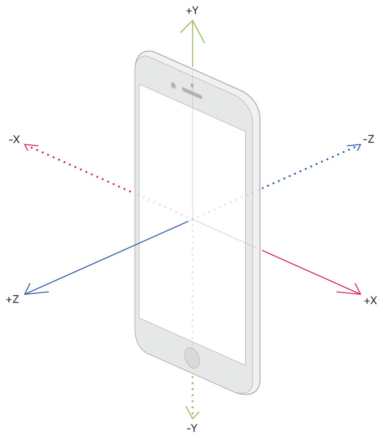
source: https://developer.apple.com/
For this experiment, and the project in general, we placed the phone screen up on the stepper motor which is located on the print head.
As a primary tool for this project, we are using a smartphone which has the Matlab app installed to log accelerometer data. We are then able to process this data in Matlab to distinguish between functioning and malfunctioning prints. This system provides an easy to use MEMS sensor in the smartphone, which is oriented in the smartphone as shown above.
3D printers
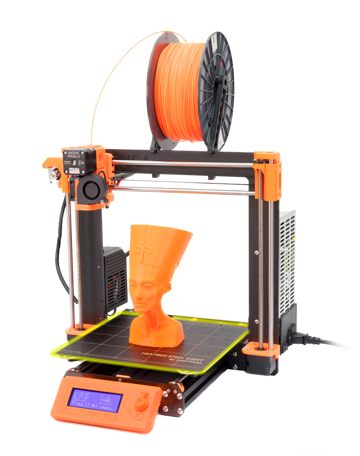
 source: https://blog.prusaprinters.org
A Prusa i3 MK3 3d printer. One of the models which we use frequently at Olin and one which is both popular and easy to modify or adapt to one's needs.
A 3d printer is a manufacturing device which heats up plastic "filament" and deposits it in programmed locations.
G-Code
Virtually all FDM 3D printers are controlled using G-Code files, which specify precise movement commands for a 3D printer to follow. We hand-wrote custom G-Code scripts based on Marlin-style G-Code to control the motion of the printer along known shapes that can be defined as parametric curves and analyzed under our motion model. Here is a hand-written G-Code file, documented inline, that moves the extruder in a convenient box, which can be useful in characterizing mid-frequency (~25-50Hz) stepper noise that could indicate a failure:
    M82 ;absolute extrusion mode
    G21 ; set units to millimeters
    G90 ; use absolute positioning
    M82 ; absolute extrusion mode

    G28 W ; home all without mesh bed level
    ; G80 ; mesh bed leveling
    G28 X0.00 ; home all without mesh bed level

    G0 X0.00 ; go to X=0
    G0 Y0.00 ; go to Y=0
    G0 Z0.00 ; go to Z=0
    ; currently should be at bottom left corner

    M107 ; turn off fan

    G0 X50.00 ; go to X=50
    G0 Y50.00 ; go to Y=50
    ; currently should be a little inwards from bottom left corner

    G0 X200.00 ; go to X=200 (bottom right corner of square)

    G0 Y200.00 ; go to Y=200 (top right corner of square)

    G0 X50.00 ; go to X=50 (top left corner of square)

    G0 Y50.00 ; go to Y=50 (return to bottom left corner of square)
This G-Code takes advantage of absolute positioning to maintain a record of desired locations of the extruder at each step. We can compare filtered experimental data collected along this path with previous filtered results to diagnose unexpected behaviors.
Stepper Motors
Stepper motors are a type of electrical motor which most 3d printers use to operate both the filament feeder and the gantry which moves the print head (which houses the feeder) around. They are composed of wire coils which produce magnetic fields, when, if programmed correctly, rotate a rotor.
Most of these motors, especially hobbyist ones, do not contain an internal feedback mechanism such as an encoder. As a result, it isn't obvious when a "step" has been skipped in the control of the stepper in most cases. In some systems, people attach encoders to the stepper outputs to track that data and correct for it.
Stepper motor resource:
https://cdn-learn.adafruit.com/downloads/pdf/all-about-stepper-motors.pdf